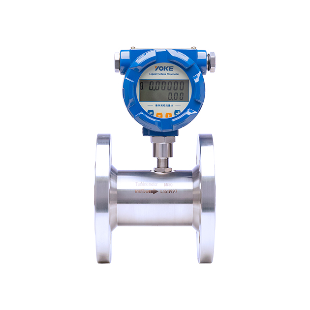
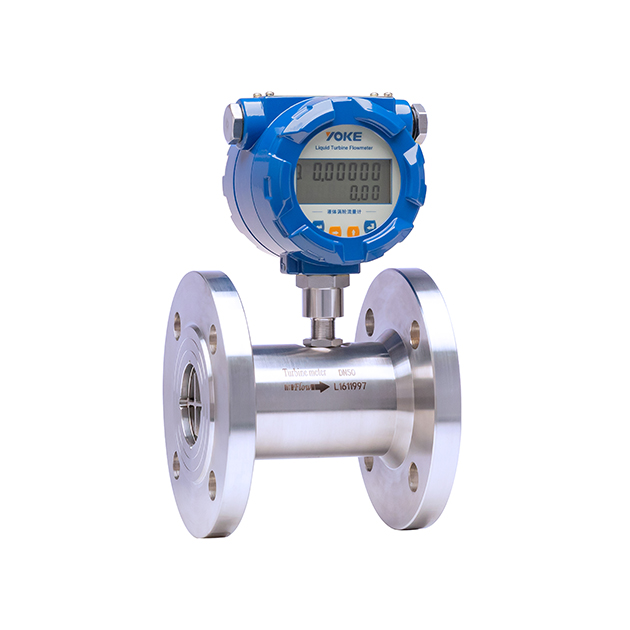
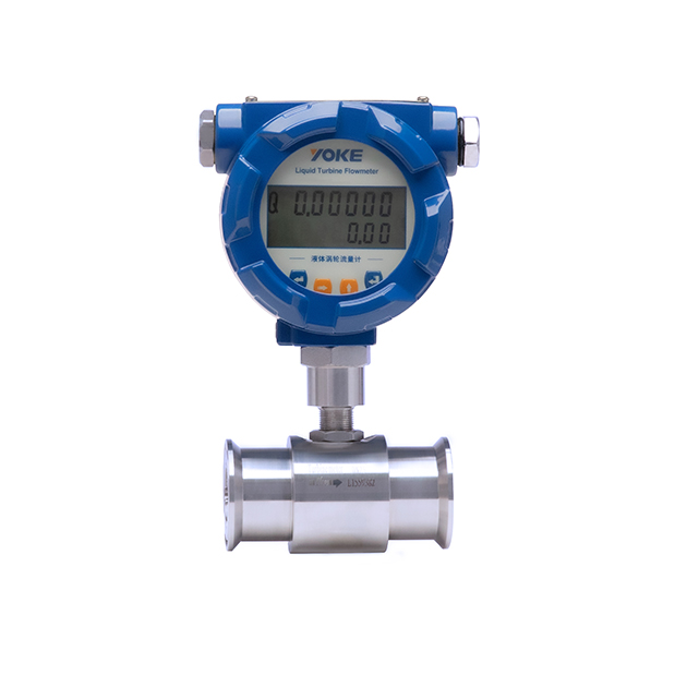
The structure of the turbine flow sensor (Figure 1) is that when the measured fluid flows through the sensor, the impeller is forced to rotate under the action of the fluid, and its speed is proportional to the average flow velocity of the pipeline. The rotation of the impeller periodically changes the magnetic resistance value of the magneto electric converter, and the magnetic flux in the detection coil changes periodically, generating an induced potential with the same frequency as the rotation, that is, an electrical pulse signal. After amplification by an amplifier, it is sent to the display instrument for display.
The flow equation of a turbine flowmeter is:
Qv=f/K (1)
Qm=qv ρ (2)
In the formula, qv, qm... respectively represent volumetric flow rate, m3/s, mass flow rate, kg/s;
The frequency of the flowmeter output signal, Hz;
The instrument coefficient of the flow meter, P/m3.
The relationship curve between the coefficient of the flowmeter and the flow rate (or pipeline Reynolds number) (Figure 2), the instrument coefficient can be divided into two segments, namely the linear segment and the nonlinear segment. The linear segment is about two-thirds of its working segment, and its characteristics are related to the sensor structure size and fluid viscosity. In the nonlinear segment, the characteristics are greatly affected by bearing friction and fluid viscous resistance. When the flow rate is below the lower limit of the sensor flow rate, the instrument coefficient changes rapidly with the flow rate, and the pressure loss is approximately proportional to the square of the flow rate. When the flow rate exceeds the upper limit, attention should be paid to preventing cavitation. The shape of TUF characteristic curves with similar structures is similar, with only differences in the level of systematic error.
1. Good repeatability, short-term repeatability can reach 0.05%~0.2%. It is precisely because of its good repeatability that it can achieve extremely high accuracy through regular calibration or online calibration, and is commonly used in trade settlement;
2. High precision, generally up to ± 1% R, ± 0.5% R, and high-precision models up to ± 0.2% R;
3. Output pulse frequency signal, no zero drift, strong anti-interference ability;
4. It can obtain high frequency signals (3-4kHz) with strong signal resolution;
5. Wide range, with a medium to large caliber of up to 1:20 and a small caliber of 1:10;
6. Compact and lightweight structure, easy installation and maintenance, and high circulation capacity;
7. Suitable for high voltage measurement, there is no need to open holes on the instrument body, making it easy to make high voltage instruments;
8. Can be made into an insertion type, suitable for measuring large diameters, with low pressure loss, low price, can be removed without interruption, and easy installation and maintenance.
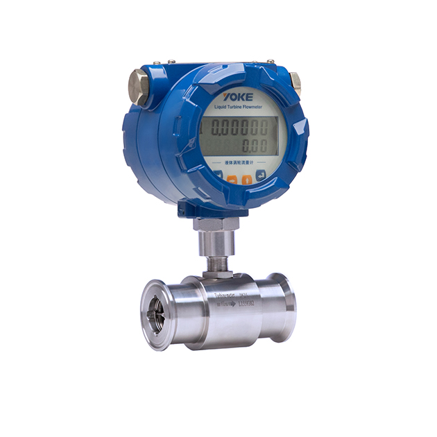
Nominal diameter(mm) | Thread connection: DN4~DN40 Flange connection: DN15~DN200 |
Execution standard | Turbine flow sensor (JB/T9246-1999) |
Accuracy level | ±1%, ±0.5%, ±0.2% (Special customization) |
Range ratio | 1:10;1:15;1:20 |
Instrument material | 304 stainless steel, 316 (L) stainless steel, etc |
Medium Temperature Range | -20~+80℃;-20~+120℃;-20~+150℃; |
Ambient condition | Temperature -10~+55 ℃, relative humidity 5%~90%, atmospheric pressure 86~106kPa |
output signal | Pulse , 4-20mA, RS485 Modbus protocol, HART protocol, etc. |
Power supply | External power supply: 24VDC±15%, ripple≤±5% Internal power supply: 3.6V lithium batteries |
Signal transmission line | STVPV3 × 0.3 (three wire system), 2 × 0.3 (two wire system) |
transmission distance | ≤1000m |
Electronic interface | Hosemann Connector, M20*1.5, NPT, etc |
Explosion proof grade | ExdIICT6 |
Protection level | IP65 |