Home
About
Introduction
Honor
Video
Join Us
Products
Flow Meter
Level Meter
Temperature And Pressure Gauge
Water Quality Analysis Instrument
Cases
Petroleum
Chemical
Environmental
Power
New Energy
Medicine
Food
News
Dynamic state
Q&A
Contact
400-0411-579
CN
CN
EN
CN
Home
About
Introduction
Honor
Video
Join Us
Products
Flow Meter
Level Meter
Temperature And Pressure Gauge
Water Quality Analysis Instrument
Cases
Petroleum
Chemical
Environmental
Power
New Energy
Medicine
Food
News
Dynamic state
Q&A
Contact
400-0411-579
Specializing in Industrial Measuring Instrument
R&D, Design, Production, Sales, Technical services, and Import and Export
24
year
Established in 2001 topresent day
100
+
Serving global countries and regions
60,000
+
Annual shipmentvolume
500,000
+
Accumulated customerservice
Flow Meter
Level Meter
Temperature And Pressure Gauge
Water Quality Analysis Instrument
Coriolis Mass Flowmeter
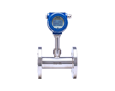
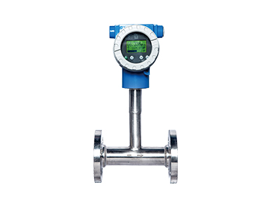
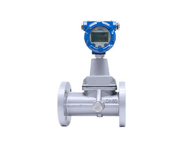
Thermal Gas Mass Flowmeter
Electromagnetic Flowmeter
Vortex Flowmeter
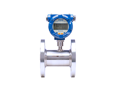
Liquid Turbine Flowmeter
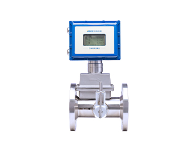
Gas Turbine Flowmeter
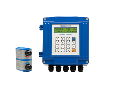
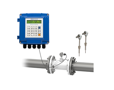
Ultrasonic Flowmeter
Target Flowmeter
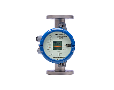
Metal Tube Float Flowmeter
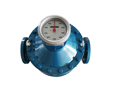
Oval Gear Flowmeter
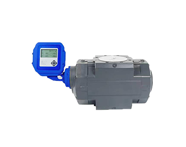
Gas Waist Wheel (Roots) Flowmeter
Precession vortex flowmeter
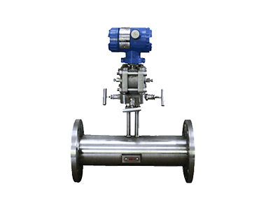
V-Cone/Orifice Flowmeter
Ultrasonic Heat Meter/Water Meter
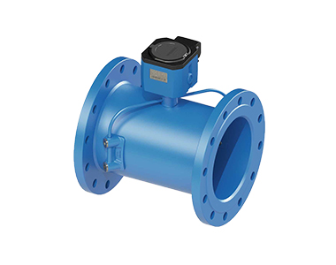
Industrial Ultrasonic Water Meter
Ultrasonic Open Channel Flowmeter
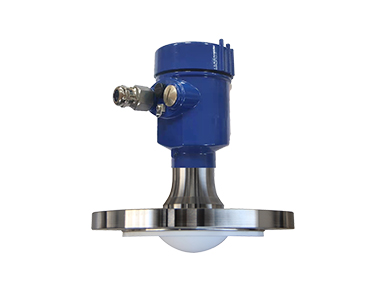
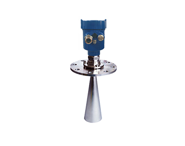
80G FM Radar Level Gauge
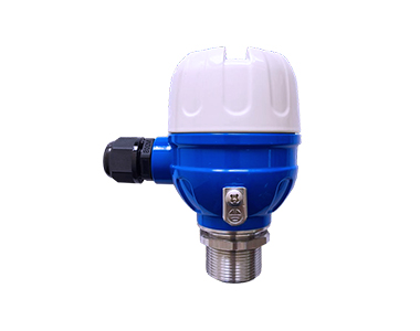
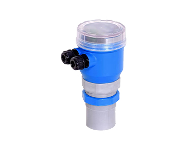
Small Blind Spot Ultrasonic Level Gauge
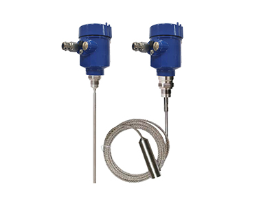
Guided Wave Radar Level Gauge
Integrated Ultrasonic Level Gauge
26G FM Radar Level Gauge
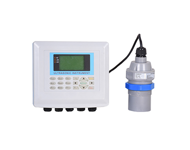
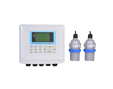
Split Type Ultrasonic Level Gauge
Single/Double Flange Level Gauge
Ultrasonic Level Difference Sensor
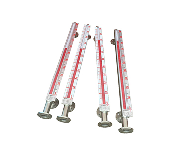
Magnetic Flap Level Gauge
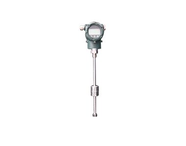
Magnetostrictive Liquid Level Meter
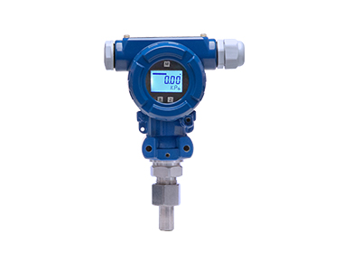
Intelligent Pressure Transmitter
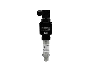
Exquisite Pressure Transmitter
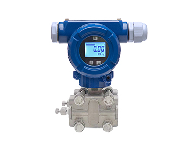
Differential Pressure Transmitter
Diaphragm Pressure Transmitter
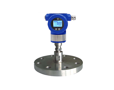
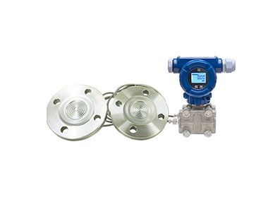
Single Flange Liquid Level Differential Pressure Transmitter
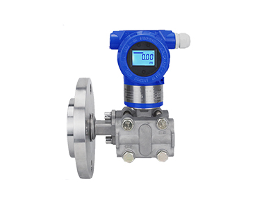
Double Flange Liquid Level Differential Pressure Transmitter
Temperature Transmitter
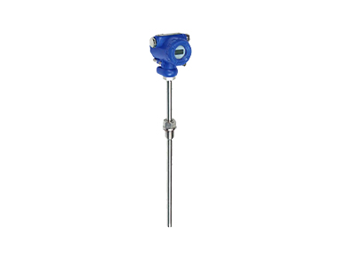
Thermal Resistance/Thermocouple
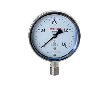
Pressure Gage
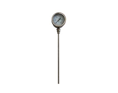
Bimetal Thermometer
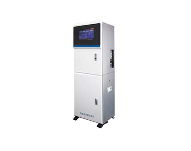
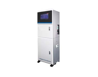
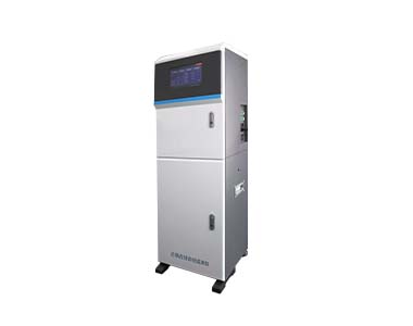
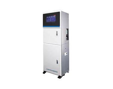
COD Water Quality Online Analyzer
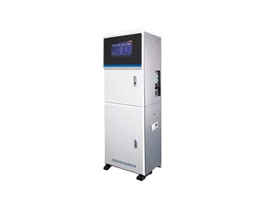
Multi Parameter (Conventional Five Parameter) Analyzer
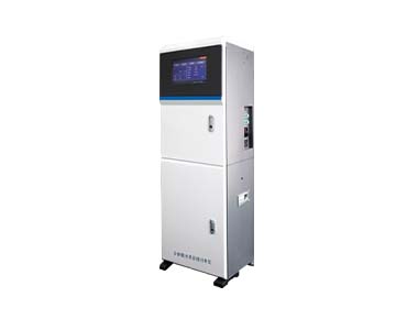
Ammonia Nitrogen Water Quality Online Analyzer
Multi Parameter Water Quality Online Analyzer
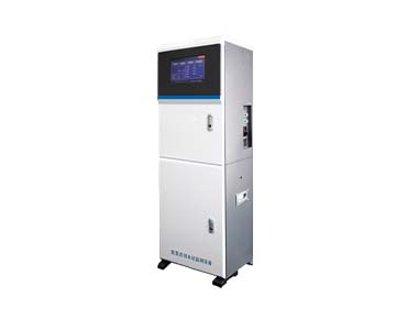
Total Phosphorus Water Quality Online Analyzer
Permanganate Water Quality Online Analyzer
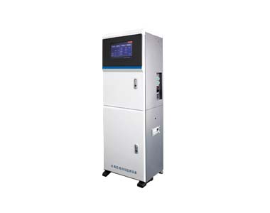
Total Nitrogen Water Quality Online Analyzer
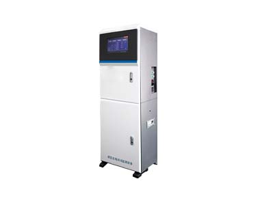
Nitrous Nitrogen Water Quality Online Analyzer
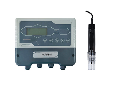
PH/ORP Meter
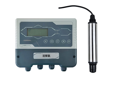
Dissolved Oxygen Meter
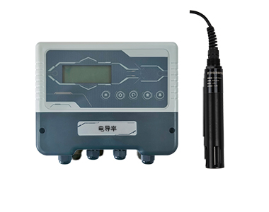
Conductivity Meter
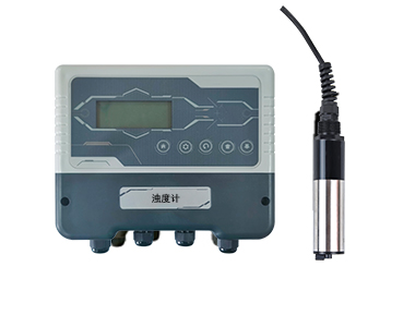
Turbidimeter
BOD Water Quality Online Analyzer
Heavy Metal Online Analyzer (Copper)
Heavy Metal Online Analyzer (Chromium)
Heavy Metal Online Analyzer (Nickel)
Service Cases
Petroleum
Chemical
Environmental
Power
New Energy
Medicine
Food
YOKE News
←
→
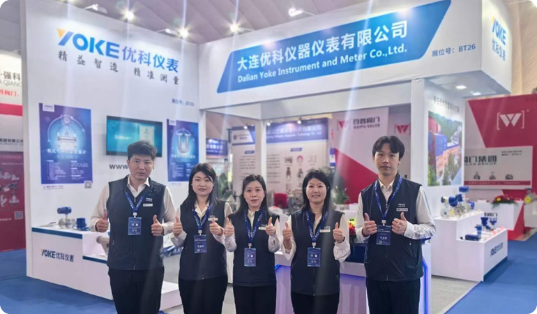
Exhibition Review | The 8th China (Zibo) Chemical Technology and Equipment Exhibition has come to a successful conclusion
Exhibition Direct | UCO Instruments Debuts at the 2024 Hannover International Industrial Exhibition in Germany
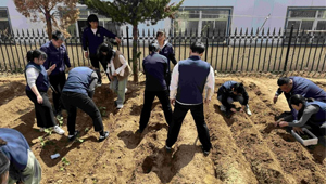
Planting Spring Colors and Exciting Plowing - YOKE Instrument Spring Plowing Activity
F&Q
Three key points to note for vortex flowmeter in mixed phase measurement media
→
Spiral vortex flowmeter has a wide flow range and is easy to install and use
→
Solution to Zero Drift Problem of Electromagnetic Flow Meter
→
Is the accuracy of the turbine flowmeter 0.5%
→
Customer Witness
Home
About
Introduction
Honor
Video
Join Us
Products
Flow Meter
Level Meter
Temperature And Pressure Gauge
Water Quality Analysis Instrument
Cases
Petroleum
Chemical
Environmental
Power
New Energy
Medicine
Food
News
Dynamic state
Q&A
Contact
Official account
Tiktok
Copyright: Dalian YOKE Instrument Co., Ltd
Record number: Liao ICP No. 09008196-2
Address: No. 3, East District, Tangli Industrial Park, Ganjingzi District, Dalian City, Liaoning Province
Email:info@ykyb.cn
Design development:联合企邦
Home
Tel
Email
Top
400-0411-579
info@ykyb.cn